As mundane and simplistic as it sounds, after safely arriving with a water source at a fire scene, a pumper’s next priority is “putting the wet stuff on the red stuff.”
That entails operating at least two valves: one from an onboard water tank to the pump and one from the pump to a discharge. Additional valving might be used if an external water supply is required from a pressurized source such as a hydrant or another rig.
National Fire Protection Association (NFPA) 1900, Standard for Aircraft Rescue and Firefighting Vehicles, Automotive Fire Apparatus, Wildland Fire Apparatus, and Automotive Ambulances, describes the 2½-inch discharges required on fire apparatus intended for structural fire attack. The controllers used to operate them is the subject of this article. The commentary is applicable to valves for preconnects, hose reels, and water tank connections. No preference or recommendation is made. The intent is to make purchasers aware.
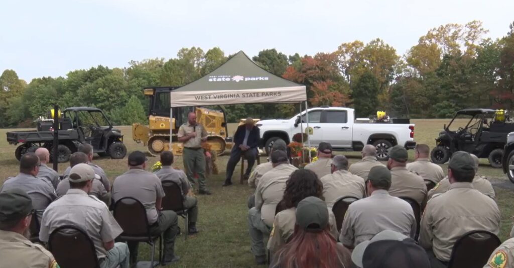
1 Midship-mounted pumps have changed little since the late 1930s. Shown is a 1938 Mack pumper being restored before the pump house was installed. The upper hand wheels control the tank fill and booster reel valves. The lower controls the tank-to-pump valve. (Photos 1 and 2 by author.)
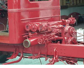
2 The same rig after the pump has been enclosed shows external 2½-inch valves with swing-to-open controls.
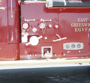
3 A side view of a Rosenbauer showing two pistol-grip style controllers for crosslay discharges. (Photos 3 and 4 courtesy of Rosenbauer America.)
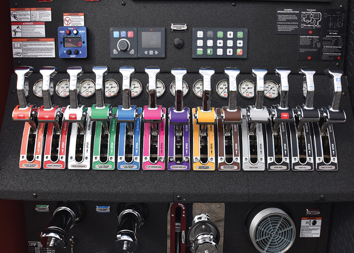
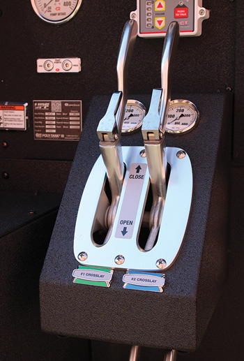
4 A Rosenbauer side-mount panel showing 13 pistol grip controllers in a row. From left to right, they are labeled for a front bumper discharge, two crosslays, two driver-side 2½-inch discharges, an officer-side 2½-inch discharge, an officer-side large-diameter hose discharge, a driver-side preconnect, an officer-side preconnect, a deck gun, a hose reel, and the tank fill and tank-to-pump valves. At the bottom is a swing-up-to-open manual controller through the panel to an auxiliary 2½-inch suction valve mounted just behind it.
NFPA 1900
NFPA 1900 Chapter 13, Fire Apparatus– Fire Pumps and Associated Equipment (NFPA 1901), section 13.7* Discharge Outlets, section 13.7.1.2 states: “A minimum of two 2½-inch (65 mm) outlets shall be provided on any pump rated at 750 gallons per minute (gpm) (3,000 L/min) or greater, and a minimum of one 2½-inch (65 mm) outlet shall be provided on any pump rated at less than 750 gpm (3,000 L/min).
Appendix A, section 13.7.5.3 states: “Control of discharges on apparatus is available as pull-type actuators; flexible push/pull controls; gear-operated hand wheel controls; and hydraulic, air, and electric operators. These controls are available with either quick-operating or slow-operating valve mechanisms. The nozzle and hose reaction and ‘operational effort’ for high-flow or high-pressure discharges are critically important to many fire departments. Because of the variations in types of individuals and characteristics of operators involved with pump operations, a purchaser should carefully evaluate valve controls.” The NFPA’s descriptions of the basic types of actuators and controls are self-explanatory and need no further elaboration.
Operational Effort
Section 13.7.5.3’s last two sentences warrant repetition: “The nozzle and hose reaction and ‘operational effort’ for high-flow or high-pressure discharges are critically important to many fire departments. Because of the variations in types of individuals and characteristics of operators involved with pump operations, a purchaser should carefully evaluate valve controls.” My interpretation of these sentences is the NFPA is inferring that when high flows and high pressures are mixed with human idiosyncrasies, somebody might get hurt.
It’s not unheard of to observe pump operators bracing one foot against a running board straining to pull open a push/pull T-handle on a discharge valve. Likewise, operators have had both feet firmly planted on the ground throwing their entire body weight against that same T-handle trying to close it.
There can be several reasons why this occurs. They are not all relegated to diminutive firefighters. Cause and origin could be attributed to the design or ill-design of the discharge piping and valve control system. There is no intention to disparage apparatus manufacturers (OEMs) nor is there an accusation of shoddy workmanship. The purchaser may have inadvertently specified the wrong controller. Reputable OEMs bid and fabricate exactly what is in a purchaser’s specifications. They must walk a fine line because sometimes questioning what a prospective purchaser has specified can cost the vendor a sale.
OEMs may also be acquiescing to purchasers specifying 10 pounds of piping and controls in a 5-pound package. The result can be overcrowded pump houses, irate pipefitters, and future frustrated service providers.
Another possibility is purchasers may not be familiar with the product (controller) being specified. They could seek guidance from component part manufacturers as well as the apparatus vendors. Know what you are purchasing. What are the controller’s advantages and disadvantages? More importantly, determine the effect on the total installation. Advice is free—so is a callous after-delivery observation: “You spec’d it, you live with it.”
ACTUATOR or Controller?
Purchasers should use due diligence when researching discharge valve controllers and actuators. Dictionary descriptions are often overly simplistic. To actuate means to put in motion. Control means to operate and regulate. The terms are often used synonymously. The above mentioned NFPA 1900 Appendix A, section 13.7.5.3 wisely lumps both together as controls.
Fire departments and specification writers often use regional terminology to describe valve controllers. Perhaps they should specify exactly how they expect it to work and what they intend to accomplish rather than what to call it.
VALVE AND CONTROLLER EVOLUTION
Most early motorized apparatus midship pumps were located under the front seat with discharge valves equipped with swing-to-open handles mounted directly on the pump. When freestanding pump houses were introduced, most discharge valves were still exposed outside the panels. Controls for internally located valves for booster tank connections and chemical hose connections (booster lines) were originally turn-handle-operated similar to early shutoffs on residential exterior garden hose connections (photos 1 and 2).
After manufacturers began recessing valves behind the pump panels, the swing-to-open handles were extended through them. Many still do today (photos 8, 12, and 13). When remote valves became necessary for crosslays, deck guns, and front and rear preconnects, they were controlled by T-handle push/pull controllers extending through the panel. Soon all valve controllers followed suit.
For whatever reason, purchasers began specifying—or manufacturers began promoting—having all discharge and valve controllers in a single row, often with the corresponding gauges located directly above. Then having valve controls for crosslays located immediately beneath their respective beds became popular.
Locating controls in a single horizontal row may be aesthetically pleasing; however, the piping runs and linkage to control them became a pipefitter’s nightmare. Manually operated linkage with formed “bends” and universals in the linkage from the handles to the valves often became difficult to operate even when not flowing water. That began the introduction of electrically operated valves. Eventually, many manufacturers began a gradual shift back to functionality rather than good looks in controller locations.
There’s a propensity for purchasers to add multiple discharges on their apparatus—often far exceeding most pumps’ rated capacities. Having multiple capped and very seldom used discharges on both sides of a rig may not bother some people despite having to be piped, controlled, and paid for. Most midship-mounted full-body pumps have discharge manifolds with multiple ports on each side of the rig, enabling many valves to be installed in relatively close proximity to the side panels.
A recent trend has been using single-suction midship-mounted pumps without discharge manifolds. OEMs must fabricate manifolds that may result in many discharge valves being remote from the pump and often not in close proximity to the operator’s panel. That can be challenging when purchasers want a pump panel layout and discharge locations identical or similar to the full-body manifolded pumps they currently own.
In both types of installations, some apparatus manufacturers have been “liberal” in the number of twists and bends they install in the linkage between manual controllers and the valves. Often, the use of universals is insufficient to alleviate straining a muscle.
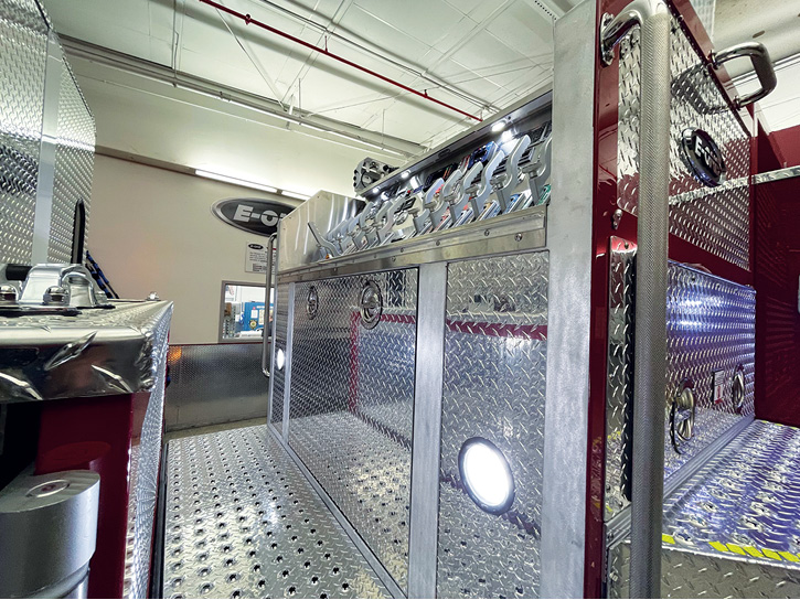
5 A top-mount E-ONE pump operator’s panel with pistol grip cable controls. Note the pump house access panels in the walkway and driver-side pump panel. (Photos 5-7 courtesy of E-ONE.)
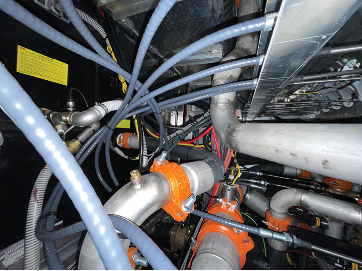
6 The inside of an E-ONE pump house with cable controls. In lieu of screwed pipe, most OEMs use flexible high-pressure hoses and welded piping with Victaulic couplings in pump houses.
THE SHRINKING PUMP HOUSE
Regardless if the intent is to maintain a short wheelbase or to gain more compartmentation, there appears to be a cooperative move by purchasers and manufacturers to lessen the physical size of traditional midship pump houses. Often, pump operator panels and pumps are remotely located.
Irrespective of the reasoning why pump house sizes are shrunken or where the fire pump and operator’s panel are physically located, many purchasers want the exact number of discharges and suctions in a smaller footprint. Credit must be given to OEMs because most will design and fabricate piping installations to meet customers’ requirements—although some may be at a healthy cost. Discharge controllers are an important part of that package.
FIREFIGHTER SAFETY
Some purchasers believe every NFPA-compliant apparatus is automatically safe and efficient for firefighters to operate. That is not necessarily true. Anticipate possible pump operator error as well as possible future changes in tactics and strategies. Visualize a firefighter waiting for a line to be charged while squatting in a precarious position inside a structure. Consider one perched on a snow-covered porch roof or on a ground ladder waiting for water to make entry through a second-floor window. Anticipate one standing alone in a slippery ice-covered parking lot waiting for the line to be charged to douse a raging car fire. Predict what could happen if an excited pump operator quickly yanks open a discharge valve.
There’s an undiplomatic and derogatory saying in the fire service that “the higher the flames are, the louder radio transmissions get.” It could be modified to say that “the higher the flames are, the more chance a pump operator might jerk open a discharge.” Sometimes adrenaline can overcome training to always open and close handline valves slowly.
NFPA 1900 section 13.7.5.3 states a slow-operating valve is required for all discharge valves larger than 3 inches. It is admirable not blowing apart the piping in a building’s fire department sprinkler connection or air launching an improperly secured ground monitor. Equal consideration should be given to not sending airborne the firefighters waiting for water. Is it feasible to voluntarily specify slow-operating (crank vs. push/pull) or even slow-closing valve controllers on any discharges that can be used for handlines?
Some departments specify oversized piping and valves for all normally piped 2-inch preconnects, thereby allowing hose size changes or adding nozzles suitable for flows in excess of 200 gpm in the future. (See NFPA 1900 Appendix A section *A.13.7.3.) Consequently, today’s preconnect could be supplied with piping and valves capable of flowing three times as much. Is it possible to overpump a preconnect?
COMPONENT PART SUPPLIERS
Although some fire apparatus manufacturers fabricate their own cabs, chassis, and bodies, purchasers should realize all are basically assemblers of component parts. Some fire equipment vendors have to be knowledgeable in a multitude of products from the apparatus and its components to ancillary equipment like turnout gear, hose, and nozzles. It might be advisable for purchasers to educate themselves. That’s a diplomatic way of saying trust but verify what you are being told.
When evaluating discharge valves and controllers, purchasers can consult their manufacturers. Akron Brass (bit.ly/3x3Anrj) and Elkhart Brass (bit.ly/43xpudi) are two major suppliers of discharge valves and their controllers. Innovative Controls (bit.ly/3x40qPg) is a major supplier of valve controls.
Most fire pump manufacturers offer prebuilt fire pump modules (bit.ly/3IQE7iI) that incorporate outsourced discharge controllers: Waterous (bit.ly/3PzjaMZ), Hale (bit.ly/3vpW2tk), and Darley (bit.ly/3VuxYzV) are suppliers of prefabricated pump modules. Ask them what discharge controllers they use or recommend—and why. Make sure you are specifying the controller that’s best suited to do the job and not necessarily what looks better on a pump panel.
OEMs AND CABLE CONTROLS
Relatively new (to me) is the use of pistol grip discharge control handles with cable linkage. It warranted investigation. Jay Johnson, executive vice president of sales and marketing at Rosenbauer America, provided photos 3 and 4 showing various configurations for them. Johnson says Rosenbauer’s specifications for what it describes as its Sealed Lever Bank Controls include the following: “The pivot-to-move assembly opens and closes the valves when the user simply pivots/moves the grip up and down. To eliminate valve drift, the user will lock the valve control at the desired position by simply releasing the grip when the desired pressure is reached.”
The Rosenbauer rigs feature pistol grip valve controls (bit.ly/3TSHDiK) by Innovative Controls, a Pennsylvania-based company started in 1993 that introduced the pistol grips in 2018. I am not advocating or promoting the product. It is another tool in the vendors’ toolboxes describing an alternative controller for apparatus purchasers to evaluate. It could be a viable solution to cramped pump houses and pump operator panels.
Phil Gerace, director of sales for E-ONE, says, “E-ONE offers cable controls as an option. The cable control is actually standard on E-ONE’s top-mount eMAX pumper to accommodate the speedlays and maximize compartmentation space. E-ONE offers cable controls on both side- and top-mount panels for those customers who want to focus on ease of activation at ‘middle ground cost’ between rods and electronic controls.”
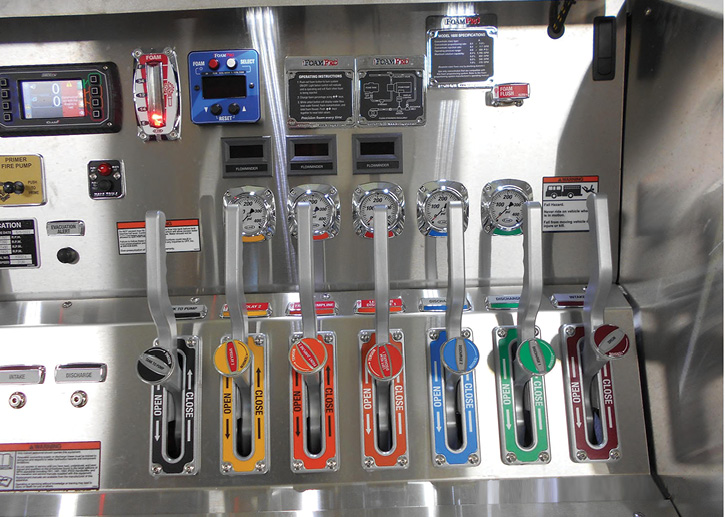
7 Another E-ONE pump panel with pistol-grip cable controls. From left to right, they are labeled tank to pump, speedlay, front jump line, left rear discharge, discharge 2, discharge 1, and intake.
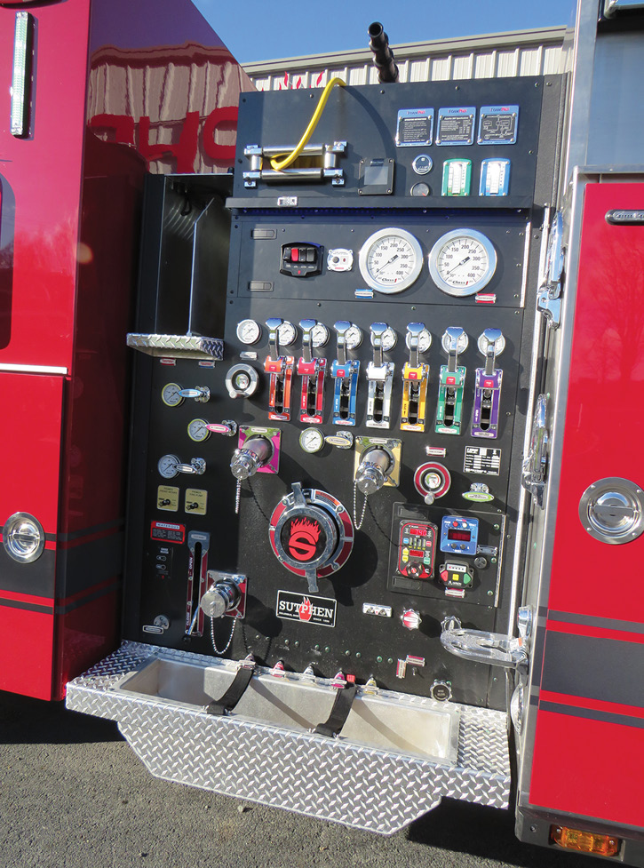
8 This North Greece (NY) Fire District Sutphen side pump operator’s panel shows three types of discharge valve controllers—pistol grip cable, push/pull, and handwheel—in addition to a swing-to-open lever to an auxiliary inlet. Controller choices can be made for ease of OEM installation and operation as well as being location- or aesthetically specific. [Photos 8-10 courtesy of the North Greece (NY) Fire District.]
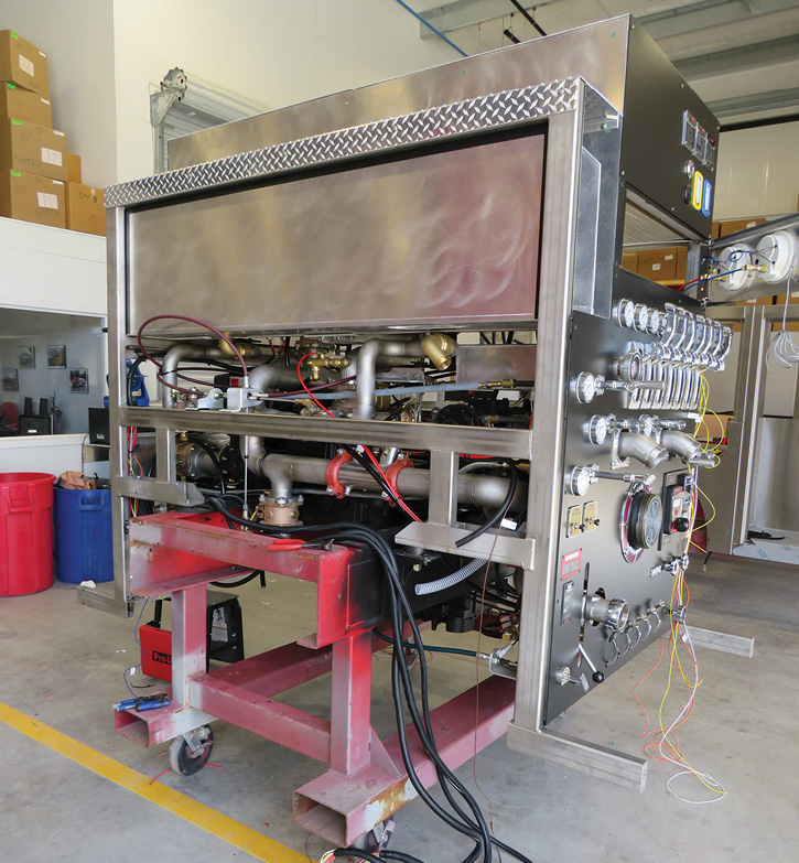
9 The pump module in photo 8 while under construction at the Sutphen facility.
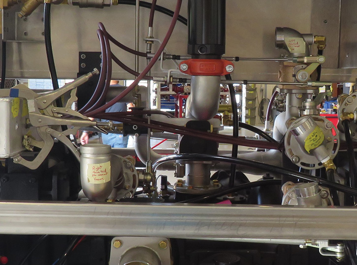
10 An interior view closeup of the same module while under construction.
Pierce Manufacturing’s Aaron Zak, fire suppression specialist, answered several questions about 2½-inch discharge controllers. His answers follow.
What is the difference between what the NFPA calls a pull-type actuator and a flexible push/pull controller? In our opinion, this NFPA language describes offering direct linkage rods vs. using rigid cable-controlled levers sometimes seen in more congested pump houses.
On midship-mounted full-body manifolded pumps, are the swing-to-open lever controllers extending through the pump panel the most popular? At Pierce, on side-mount pumpers, we find that T-handle (push-pull) controllers are most popular, with optional vertical swing levers being preferred by certain customers (photo 13). These same swing levers come standard on our top-mount pumpers where T-handles might be more awkward to operate.
On midship-mounted full-body manifolded pumps, is there a large cost differential to go from a swing-to-open lever extending through the pump panel to a push-pull T-handle controller? On a side-mount pump panel, the cost of T-handle controllers is actually about $150 less per discharge than vertical swing levers.
Are all manual controllers with cable linkage sealed? We are familiar with cable-style controllers, but at Pierce, we design and manufacture each pump house individually and locate the discharge manifold to maintain the straightest in-line linkage so that no cable-type material is required.
One pump manufacturer promotes the use of a gear-and-sector mechanism on manifold-mounted valves. Is this common to the one pump manufacturer only? We have installed rack-and-sector controllers on certain model discharge valves when specified or desired by the customer. Smooth operation and a positive locking feature in any valve position are two reported benefits.
Are manually formed bends and breaks in direct valve control linkage common? While we have seen several instances of angled bends on some competitive pump house assemblies, Pierce works hard to control “the real estate” inside every pump house to maintain straight and unimpeded linkage wherever possible. In some cases when a pump is equipped with many discharges—added crosslays/foam systems/multiple rear discharges, etc.—we might advocate for an electric controller on larger outlets to save on operational space or pump panel width.
When in-line valves (remote from the pump) are specified, is there a particular type of controller you, as an apparatus OEM, would recommend or specify? In such cases of remote mounted valves, we would typically recommend electric motor activation where wiring can be run to a pump panel controller as opposed to multiple joints in linkage.
Does having all discharge controllers in a row on a side-mounted pump panel dictate the type of controller that must be used? I’d describe this as mostly a customer preference item, but typically we find that using T-handle controls allows for neat and organized packaging in a slightly narrower pump panel. We offer a “Control Zone” feature where we locate the controls into two rows; if the truck has foam, one row of controls will be foam-capable, and the other would be for clear water. We lay out the panel “more linear” in terms of discharges around the truck, starting at the front and working rearward, with left-to-right controllers for easier operations. Using the vertical swing style can add a few inches in width for the finished metal bezel around each lever that both identifies each valve and nicely aligns with the 3½-inch pressure gauges.
Does the same apply for remote pump locations? With our PUC™ configuration, vertical swing handles for all 2-inch and 2½-inch valves fit nicely inside the enclosed pump panel compartment—with a choice of either electric controllers or handwheels used for larger 3-inch and 4-inch discharge valves.
How do you pick and choose the discharge valve controllers supplied on your apparatus? Pierce collaborates closely with our dealer representatives and customers to ensure the very best outcome in pump panel design and operations. In some cases, or on more complex apparatus, a detailed pump panel drawing can be supplied for approval, before pump house construction or assembly begins.
There are similarities in controllers in the Elkhart and Akron catalogs—any comment? Both valve manufacturers do offer the same combinations of controls whether they be simple T-handle, swing levers, rack-and-sector, and handwheel or electric motor style for larger discharges when a slower opening and closing is needed to avoid water hammers/pressure spikes. We try not to overcomplicate the most often used 2-inch and 2½-inch discharges, and they are relatively easy to operate when needed. Regardless of controller style, it is important to maintain/clean and lubricate the linkage, trunnions or stems, and related pump panel hardware. When rack-and-sector styles are used, some customers even add a rubber boot over any linkage connections that both holds in lubricating grease and keeps moisture out, for smoother actuation.
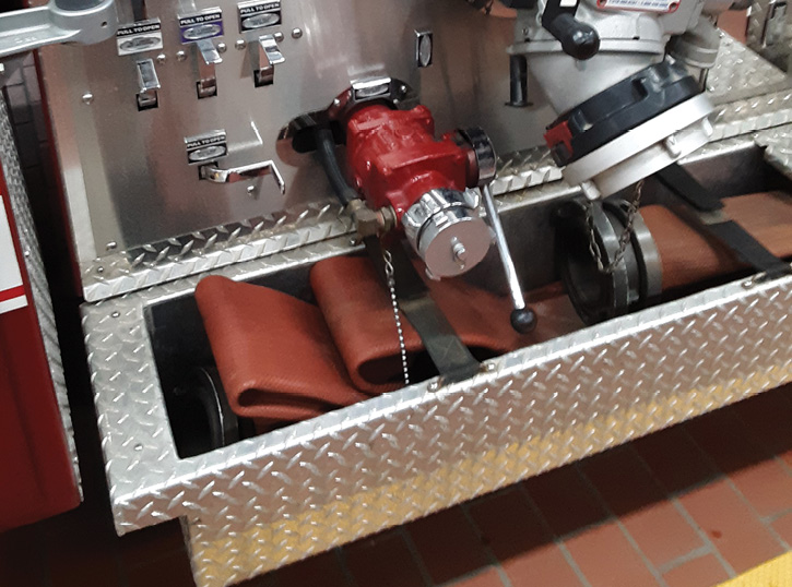
11 A view of an externally mounted 2½-inch suction valve with a swing-to-open controller. Along with the external steamer-mounted intake valve, it can cause some serious finger jamming when accessing the soft sleeve mounted in the hosewell. (Photos 11-12 by Dan Gekoski.)
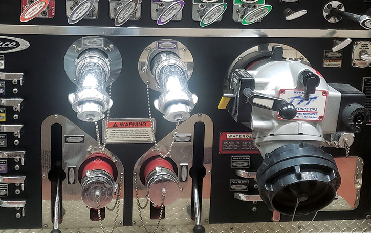
12 T-handle push-and-pull controllers are on the recessed 2½-inch discharges. The 2½-inch auxiliary suctions are mounted behind the panel with swing-to-open controls extending through it. Extra-large escutcheon plates allow servicing the suction valves without tearing apart the pump panel.
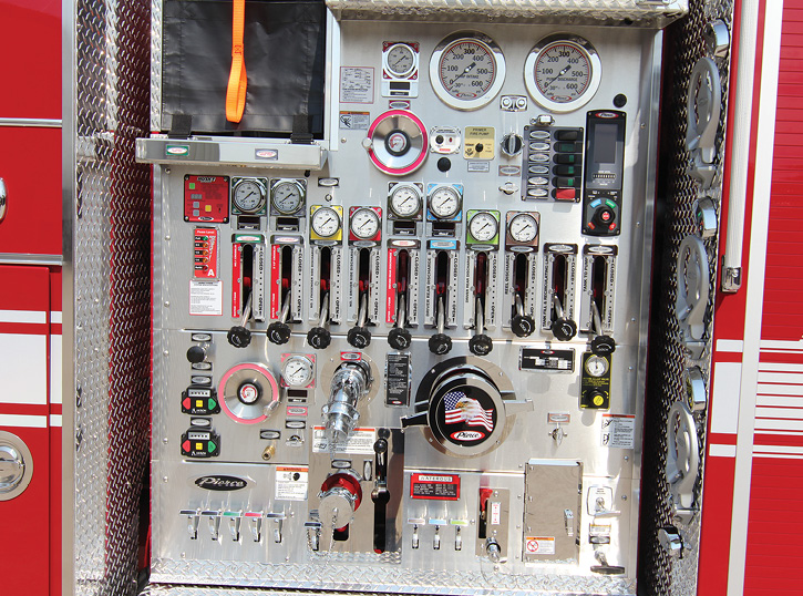
13 According to Zak, this side-mount pump panel is very organized using the vertical swing lever controller. This type of installation typically adds a couple of inches per discharge with the finished metal bezel that surrounds and identifies the control lever. A similar installation using the same number of discharges with T-handle controls can reduce a pump panel’s width significantly when a narrow panel would be advantageous for a shorter overall truck length. (Photo courtesy of Pierce Manufacturing.)
A NEW CABLE CONTROL USER
Battalion Chief Gregg Knapp of the North Greece Fire District in upstate New York provided insight on his department’s switch to cable controls. Its career firefighters in three stations located just outside of Rochester, New York, staff two engines and a quint responding to around 4,000 calls annually. Recently delivered Engine 273, a Sutphen 2,000-gpm pumper, has 12 discharges. Seven have pistol-grip cable-operated controllers, four are push/pull rod-activated, and one is hand-wheel-controlled (photo 8). Interestingly, there is a second handwheel controlled valve above the pump house directly below the monitor.
There is also a traditional swing-to-operate lever on a recessed 2½-inch auxiliary inlet on each side of the pump house. Knapp says, “The cable-operated controllers are new to us. It was challenging to make the change from all hand-wheel controls on our other Sutphens. However, the district solicited input from all of our pump operators prior to doing so. They appear to be smooth-operating, and so far the pump operators have liked them. The rig has only been in service for a short while so we don’t really have a lot of time on them per se other than training hours. We are not too sure of the long-term operation in our climate with the road salt aspect, but that is something we are watching. My only thought is that there might be the need for some type of lubrication such as a grease of some type into the cable after some time. This is something that we are going to closely monitor in our maintenance.”
Consolidating a like number of discharges, piping, and controllers into to a pump house that might be one third smaller than “normal” can be problematic but not necessarily impossible to fabricate. More than likely, it will require numerous and expensive other-than-standard manual valve controllers.
Repairing, replacing, or possibly performing maintenance on a component part inside a pump house can be arduous and expensive. After a rig’s warranty has expired, the apparatus manufacturer is no longer responsible, and the cost of repairs becomes the purchaser’s responsibility.
It may take hours just to remove and replace pump panels. Purchasers looking at a preplumbed pump house on a factory floor may get a false sense of access (photo 9). A nontilting commercial chassis negates tilting the cab to access a pump house. A nonmonetary consideration, but an important firematic one, is the hours or days a rig may be out of service for a simple repair.
If a small pump house is required for sound firematic reasons, so be it. If it is specified because it merely looks sharp or because the neighboring fire department has one, then purchasing priorities could be reevaluated. Good luck!
BILL ADAMS is a member of the Fire Apparatus & Emergency Equipment Editorial Advisory Board, a former fire apparatus salesman, and a past chief of the East Rochester (NY) Fire Department. He has 50 years of experience in the volunteer fire service.